Ultrasound Engineering
Ultrasound OEM Receiver Dynamic Range: Beyond Channel Count in 2026
How ultrasound OEM teams should assess receiver noise, gain control, overload recovery and channel consistency alongside receive-channel count.
A receiver-channel count describes acquisition capacity, not the smallest usable echo, recovery from a strong reflection, or displayed image contrast. For an ultrasound OEM platform, those questions must be evaluated across the receive path, not inferred from one headline specification.
What a current integrated receiver changes
Texas Instruments' public AFE5932 documentation, dated March 13, 2026, describes a 32-channel ultrasound receive AFE with attenuation, gain, filtering and digitization. Integration makes it possible to evaluate these functions together, but it does not remove the need for a noise and headroom budget. Here AFE5932 is a public component example, not an ALEVA product specification or a claim that ALEVA uses it commercially. The number refers to receive channels per IC, not transmit channels or an evaluation board's total. [1]
Receiver range, converter resolution and display range are different
Time gain compensation, or TGC, adjusts the receive gain with time to accommodate changing echo amplitudes. Strong returns need sufficient headroom; weaker returns need amplification without excessive added noise. This is an established principle, not a discovery introduced in 2026. TI's 2017 reference design explains why both ends of that operating range matter. [2]
A useful instantaneous input-referred range compares the largest undistorted signal with the relevant RMS noise floor, using compatible amplitude conventions and a defined bandwidth. It is not the same as a gain-control span. ADC bit depth is another quantity, and display compression is another: changing a display setting does not demonstrate that additional information was acquired.
Analog Devices' historical receiver discussion also distinguishes instantaneous conversion needs from the wider echo-amplitude range accommodated over time by TGC. Its legacy devices are background examples, not current product recommendations. [3]
Why adding channels cannot repair every receive-path problem
Coherent summation can improve signal-to-noise ratio when desired signals align and channel noise is sufficiently uncorrelated. That condition matters: shared interference is not equivalent to independent noise. More channels also do not restore waveform information already lost to clipping. Distinguish a beamforming benefit from an improvement in the analog receiver itself. [3]
What recent research adds
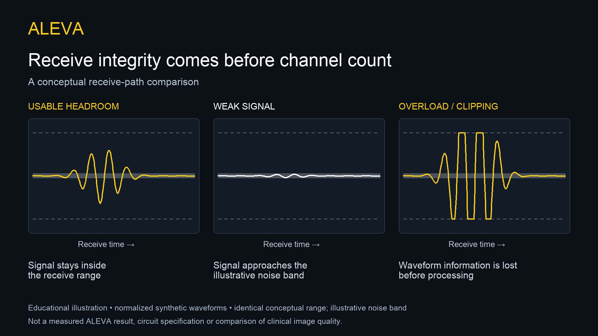
Educational illustration using normalized synthetic waveforms and an illustrative noise band. It is not a measured ALEVA result, circuit specification or comparison of clinical image quality.
A 2025 IEEE ISCAS conference paper by Dias, Costa and Goes studies a programmable-gain floating-inverter low-noise amplifier. The TU Delft repository abstract highlights trade-offs between gain-step resolution, area, power and rejection of switching interference. It supports a practical lesson: gain control is part of the integration problem, not merely a software setting. This discussion is limited to the public abstract, not an independent replication of its measurements. [4]
For context, Chen and Tsai's peer-reviewed 2024 IEEE Sensors Letters article examines dual-mode TGC involving the amplifier and converter. Its public university abstract illustrates another architecture choice; it does not establish performance equivalence with a commercial portable scanner. The paper is identified as 2024 research, not a new 2026 release. [5]
A verification plan before the schematic is frozen
The following is an engineering evaluation proposal, not measured ALEVA performance:
Noise: record input conditions, bandwidth, gain, termination and temperature.
Headroom: identify which stage overloads first under representative strong inputs.
Recovery: measure settling after overload and after gain changes against a defined acceptable-error criterion.
Consistency: use a common input to assess channel gain, timing and shared interference.
System evidence: separate electrical tests from controlled phantom studies; neither alone establishes diagnostic performance.
The OEM decision
Choose the channel architecture around probe compatibility, receive integrity, processing needs and power constraints. A larger channel count is useful only when the complete platform meets its defined requirements. ALEVA, California, USA, welcomes discussions about these trade-offs in custom ultrasound OEM engineering and beamformer development.
Sources and scope
Texas Instruments: AFE5932 public product documentation, March 13, 2026; checked October 8, 2026.
Texas Instruments: TIDA-01427 / TIDUD38, August 2017. Foundational TGC reference, not a new-device announcement.
Reeder and Petersen: AD9271 portable-ultrasound receiver discussion, historical Analog Dialogue article; no current-market specifications inferred.
Dias, Costa and Goes: A Programmable-Gain Floating Inverter Low-Noise Amplifier for Ultrasound Imaging Analog Frontends, IEEE ISCAS 2025; institutional public abstract reviewed.
Chen and Tsai: A High-Dynamic-Range Ultrasound Receiver With Dual-Mode Time-Gain Compensation, IEEE Sensors Letters 8(8), 2024; institutional public abstract reviewed.
No confidential architecture, proprietary settings, clinical outcome, certification or commercial use of a named component by ALEVA is asserted.