Ultrasound Engineering
Ultrasound TGC Control Noise: Test Across Channels
Why shared ultrasound gain-control signals need cross-channel noise and settling tests, with a bounded analytic model and source-led OEM acceptance guidance.
By ALEVA | California, USA | October 20, 2026
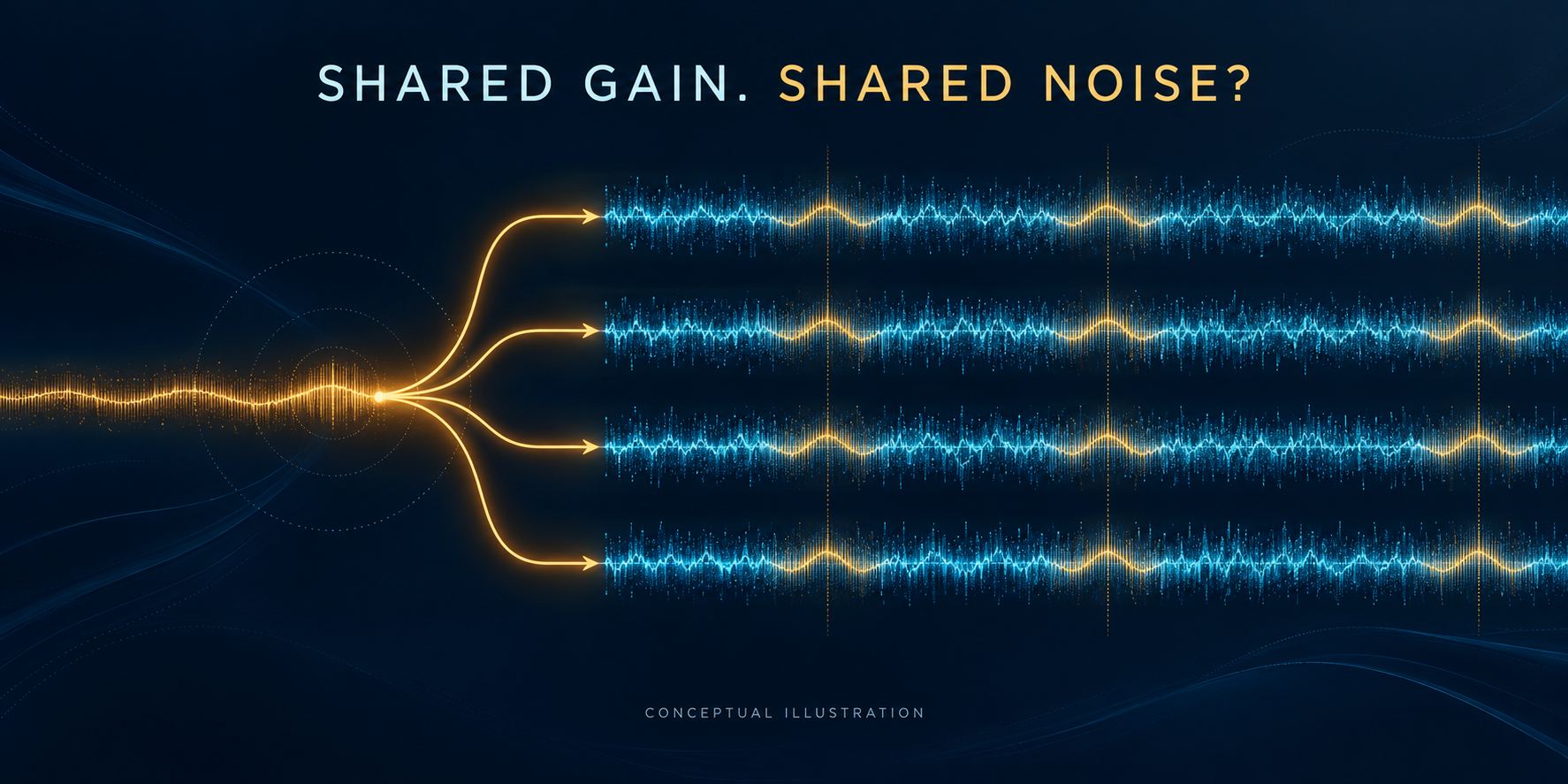
AI-generated conceptual illustration of a shared gain-control path and parallel receiver channels. The traces are illustrative, not measured waveforms or a device specification; actual coupling depends on the receiver and beamforming configuration.
Engineering question: When several ultrasound receiver channels share a time-gain compensation control signal, is a quiet single-channel trace enough to qualify the gain-control design?
A shared control is a shared noise path
Time-gain compensation changes receiver gain during acquisition. TI’s May 2023 application note SLAAE64 describes a particular risk: noise on a control voltage shared by multiple AFE channels can introduce correlated channel noise. The control generator therefore belongs in the receiver noise budget, rather than being treated as a low-frequency housekeeping circuit. This is a documented design consideration, not a newly announced component. [1]
Why correlation matters
Consider a deliberately simplified receive model: each aligned channel has an equal desired signal s, independent zero-mean noise n_i with variance σ_n², and the same additive disturbance c with variance σ_c². Assume independent noise sources, equal channel weights and identical disturbance phase. For the normalized average of N channels:
y = s + (1/N) Σ n_i + c; Var(noise) = σ_n²/N + σ_c².
The independent contribution falls with averaging; the common contribution does not. This is an analytic illustration, not a prediction for a particular probe or beamformer. Actual control-noise coupling can be signal-dependent, and receive delays, weighting and frequency-dependent correlation can change its contribution. The equation is a reason to measure cross-channel behavior, not a universal scaling law for TGC hardware.
Filtering has a timing cost
TI’s TIDA-01427 reference design, documented in August 2017, uses a filtered differential control path to drive multiple AFEs. Its topology is a historical reference, not an ALEVA implementation. [2] Our engineering inference is that a control-path filter must be evaluated against the required gain trajectory as well as noise: a quiet waveform that fails to settle at the required acquisition time is not an acceptable substitute.
A proposed OEM acceptance test
Record synchronized channel data under a defined termination or calibrated input, with the intended bandwidth and receiver configuration. Compare fixed-gain operation with the programmed TGC trajectory. Measure channel noise, cross-channel covariance and transient behavior around gain changes; then apply the intended receive delays and weights to the same data. Repeat with representative weak and strong inputs, holding display mapping fixed. Define test bandwidth, windows, temperature, loading and pass/fail thresholds in the product requirements rather than borrowing a vendor example as a system specification.
This proposed test complements our receiver dynamic-range discussion: it isolates a shared control path instead of treating every receiver limitation as a channel-count issue.
The architecture decision
Gain-control architectures are not interchangeable. Chen and Tsai’s peer-reviewed 2024 IEEE Sensors Letters paper describes a dual-mode receive architecture using VGA bypass and ADC reconfiguration; only its public institutional abstract was reviewed here. It does not establish the best architecture for another system. [3]
For an ultrasound OEM beamformer program, specify the shared-control noise path, gain timing and cross-channel acceptance evidence together. A brighter image or a low single-channel noise number alone does not close that verification task.
Sources and scope
Xu, Wang and Pithadia, Analog Time Gain Control (ATGC) Solutions for TI’s Ultrasound AFE. TI application note SLAAE64, May 2023; manufacturer technical reference.
TI TIDA-01427 differential TGC reference design. Design guide dated August 8, 2017; historical reference.
Chen and Tsai, A High-Dynamic-Range Ultrasound Receiver With Dual-Mode Time-Gain Compensation. IEEE Sensors Letters 8(8), 5502704, 2024. DOI: 10.1109/LSENS.2024.3418628. Public institutional abstract reviewed, not a full-paper replication.
Sources checked October 20, 2026. Searches prioritized 2025–2026; no newer, fully verified source was required for this narrow analysis. The sources above retain their actual dates. The model and acceptance test are engineering analysis, with no claimed commercial use of a named component by ALEVA.