Ultrasound Engineering
Plane-wave compounding: budget motion before adding angles
A research-led ultrasound OEM guide to motion-aware angle selection, acquisition timing and reproducible acceptance tests, with an explicitly illustrative calculation model.
By ALEVA · California, USA
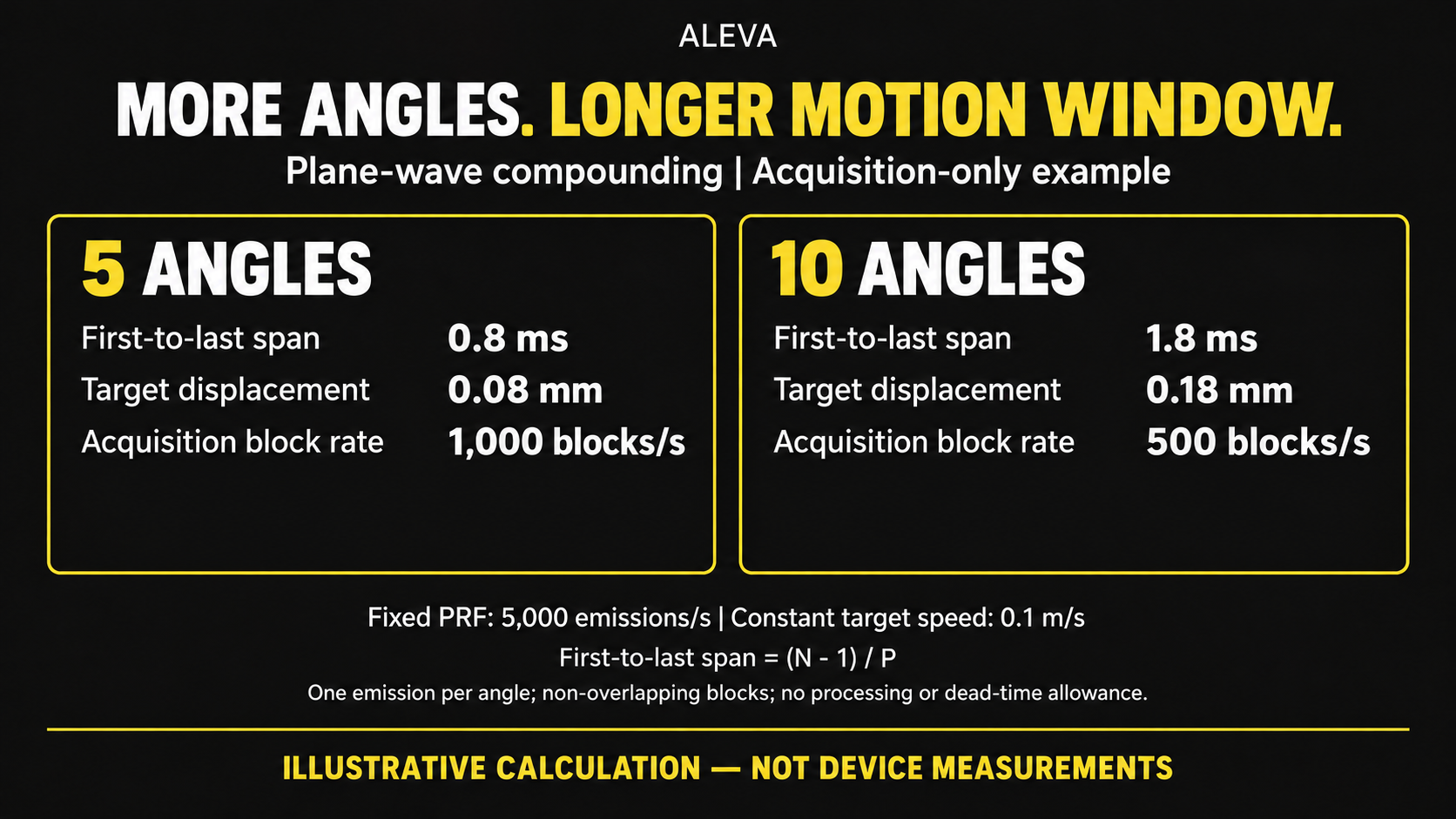
An ultrasound OEM team choosing a plane-wave sequence faces a specific question: what does an additional transmit angle cost in acquisition time, and can the intended target remain sufficiently consistent across that time? A static image alone cannot answer it. The useful specification connects the sequence to a defined motion test and a separately measured reconstruction pipeline.
What recent research does—and does not—establish
Jang and colleagues investigate angle distribution and reconstruction-grid choices in plane-wave synthetic focusing. Their peer-reviewed Scientific Reports paper was published online on December 4, 2025, in a 2026 volume. It treats angle selection as part of a resolution, computation and imaging-rate trade-off, not as a universal angle-count recommendation. Its setup-specific findings are not an ALEVA product specification. Jang et al., DOI 10.1038/s41598-025-30595-0.
Khetan and Mertz examine joint coherence factor weighting at the transmit-angle/receive-position level. That is a distinct reconstruction method, not a generic guarantee that weighting corrects all motion. Their article appeared online January 22, 2025, with the journal issue in May 2025; the author manuscript's 2026 PMC availability does not make it a new 2026 algorithm. Publication record, DOI 10.1016/j.ultras.2025.107573.
A further peer-reviewed study by Khairalseed, Zhang and Bell examines reducing angular compounding specifically for coherence-based sound-speed estimation. It appeared online in December 2025 and in the April 2026 Ultrasonics issue. A sufficient angle set for that estimator should not be transferred unchanged to a different imaging or motion-tracking requirement. Publication record, DOI 10.1016/j.ultras.2025.107915.
A reproducible acquisition-only planning model
This is an illustrative arithmetic model, not a simulation of image quality or a device measurement. Assume a constant pulse repetition frequency P, one emission per angle, N angles per non-overlapping compounded image, no reuse of emissions and no interleaved modes.
Emission-to-emission spacing is 1/P. The first-to-last emission span is (N−1)/P, while the interval between the starts of successive complete N-emission blocks is N/P. Their acquisition-only frame rate is P/N. A target moving at constant speed v travels v(N−1)/P between the first and last emissions.
Illustrative inputs: P = 5,000 emissions/s and constant target speed v = 0.1 m/s. Values are calculated, not recommended operating settings.
Angles N | First-to-last span | Acquisition-only block rate | First-to-last displacement |
|---|---|---|---|
5 | 0.8 ms | 1,000 blocks/s | 0.08 mm |
10 | 1.8 ms | 500 blocks/s | 0.18 mm |
These displacement values do not predict resolution, phase error, contrast or clinical performance. The model omits receive-window duration, switching and recovery constraints, pauses, output limits and processing. Actual scheduling and safe acoustic operating limits require project-specific engineering and validation.
Turn the trade-off into an acceptance test
For a proposed OEM evaluation, define the target trajectories and directions first. Include a stationary control, controlled repeatable motion and conditions that challenge the sequence. Freeze probe identity, acquisition depth, aperture, gain, preprocessing, weighting and display mapping unless one of those is the variable being tested.
Test question | Record separately |
|---|---|
Does the sequence tolerate the specified motion? | Angle order, transmit timestamps, trajectory, repeats and relevant image or tracking error metric. |
What was reconstructed? | Raw-data identifier, channel map, calibration version, algorithm and reconstruction-grid settings. |
Can the pipeline sustain operation? | Delivery rate, dropped captures, processing time, memory use and thermal test conditions. |
When was the image available? | Acquisition completion, reconstruction completion and displayed-frame timestamps, with clock alignment documented. |
Compare a documented delay-and-sum reference with a candidate method using the same available inputs. Avoid changing the display treatment while claiming that a brighter or cleaner image proves an algorithmic gain. Image contrast, spatial resolution, motion tracking and latency answer different questions; the relevant metrics and tolerances should be specified before running the comparison.
What an OEM/ODM decision should deliver
The deliverable is a tested operating envelope, not an impressive maximum angle count. Record the selected angle set and order, allowed scheduling behavior, applicable motion conditions, reconstruction version and failure cases. Where the host receives subarray outputs rather than independent element data, state that constraint before promising an algorithm comparison.
ALEVA can discuss these requirements within ultrasound OEM development and beamformer engineering. Our transmit, receive and probe-boundaries guide explains why access to the required inputs must be established first. This article proposes an engineering evaluation workflow; it does not claim implementation in an ALEVA commercial product or improved clinical outcomes.
References and editorial scope
Jang D. et al. Investigation of ultrasound plane-wave imaging for optimal synthetic focusing. Scientific Reports 16, 1057 (2026), online December 4, 2025. DOI 10.1038/s41598-025-30595-0.
Khetan N., Mertz J. Plane wave compounding with adaptive joint coherence factor weighting. Ultrasonics 149, 107573 (May 2025), online January 22, 2025. DOI 10.1016/j.ultras.2025.107573.
Khairalseed M., Zhang J., Bell M.A.L. Minimal angular compounding required for coherence-based sound speed estimation with plane wave ultrasound imaging. Ultrasonics 160, 107915 (April 2026), online December 2025. DOI 10.1016/j.ultras.2025.107915.
Sources checked October 11, 2026. Peer-reviewed studies are distinguished from availability dates. No patient data, confidential architecture, proprietary code, customer identities or unpublished ALEVA measurements were used. The figure and arithmetic table are illustrative calculations, reproducible from the stated inputs, not device measurements.