Ultrasound Engineering
Ultrasound OEM Beamforming: Define the Transmit, Receive and Probe Boundaries
A requirements-led guide to transmit timing, receive reconstruction and in-probe channel reduction, with public TI documentation and a 2025 IEEE JSSC paper and correction.
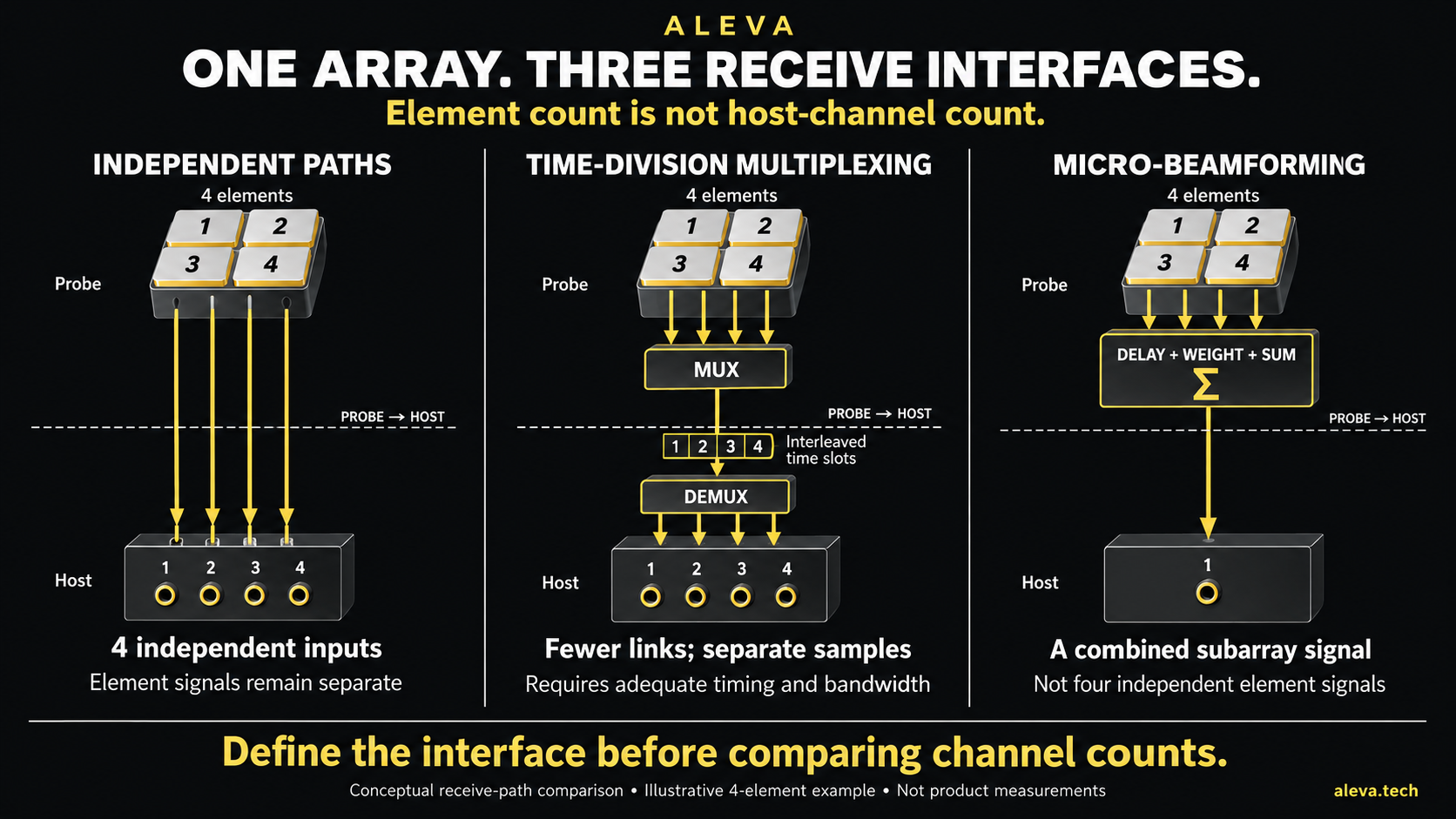
Conceptual receive-path comparison using an illustrative four-element array. Multiplexing and micro-beamforming are different operations; this diagram does not represent measured ALEVA hardware or a universal channel-count recommendation.
When a component description says “integrated beamformer,” what does the integration actually include? For an ultrasound OEM project, the useful answer is a signal-path definition: which excitation timing is generated, which echoes are acquired, and which channel information remains available to reconstruction software.
Transmit timing is not receive reconstruction
Transmit beamforming coordinates excitation across an array. Receive beamforming combines returning signals with delays and weights appropriate to the reconstruction. A device implementing the first job does not, by that fact alone, implement the second.
Texas Instruments' TX73H32 is a public example: TI describes a 32-channel transmitter integrating pulsers, transmit/receive switches and a transmit beamformer. Its listed Rev. A datasheet is dated November 25, 2024; it is not a newly launched 2026 part. Separately, TI's AFE5932 product documentation dated March 13, 2026 describes a 32-channel receive AFE with attenuation, gain/filtering and ADC functions. These are functional examples, not a recommended pairing or a claim that ALEVA uses either device commercially. TX73H32 documentation; AFE5932 documentation.
Probe elements and host channels are different counts
In-probe micro-beamforming and multiplexing can change what reaches the main system. Multiplexing preserves distinguishable signals only to the extent supported by the actual sampling, transport and demultiplexing design. Combining signals in a subarray is a different operation: the host receives combinations, not automatically independent samples from every element.
A peer-reviewed 2025 IEEE Journal of Solid-State Circuits paper by Rozsa and colleagues provides a concrete research example. Its institutional abstract describes a 4096-element CMUT probe using both 2 × 2 delay-and-sum micro-beamforming and 2× time-division multiplexing for an 8× receive channel-count reduction. It describes a separate programmable transmit beamformer. This illustrates distinct operations within one probe, not a universal architecture for commercial matrix probes. Rozsa et al., 2025.
The same work has a published correction. The authors explain that the original Figure 6 timing diagram incorrectly implied a 10 MHz TDM rate; the corrected diagram indicates 20 MHz and avoids omitted samples in the illustrated switching sequence. This is a correction to that diagram, not evidence of a defect in every multiplexed probe. Review the correction alongside the original paper before reproducing its timing. Correction, 2025.
Write an interface contract before choosing a channel headline
Boundary | What to specify | Evidence to request |
|---|---|---|
Sequencer to transmit electronics | Pulse pattern, delay convention, update timing and supported load | Electrical timing traces for representative sequences and loads |
Transmit to useful receive acquisition | Protection, blanking interval and the criterion for a valid sample | Recovery measurements at the complete receive-path output |
Probe to host | Element mapping, subarray combination, multiplexing and calibration dependencies | A documented mapping and measured reconstruction of the transported signals |
Acquisition to reconstruction | Sample timestamps, channel identifiers, RF/IQ representation and missing-data policy | Replayable test data and a numerical reference appropriate to that interface |
These are proposed verification items, not ALEVA test results. Acceptance limits must be derived from the intended probe, sequence, imaging task and complete architecture.
The trade-off is access, timing and implementation burden
Moving processing into a probe can simplify a downstream interface, but it also moves requirements for configuration, calibration, power and verification. Retaining more independent element data can give reconstruction software more choices, while requiring the transport and storage system to carry that information. Neither route is intrinsically the best choice for every product.
For example, if an algorithm needs element-level inputs but the probe exports fixed subarray sums, adding host processing channels does not make those original inputs independently available. Conversely, a multiplexed interface should not be treated as lossy beamforming merely because fewer physical links are used. Ask what is sampled, what is combined and what is recoverable.
A practical OEM decision
Compare candidate architectures against the same interface contract. First define the data needed by the intended algorithms; then choose the probe-to-host boundary and verify timing, recovery and calibration at that boundary. Only then is a channel-count comparison meaningful.
This approach does not establish a universal optimum of 192, 256 or any other host-channel count. That decision needs a specified aperture, probe architecture, acquisition strategy and cost/power constraints. Public research results from one prototype are not performance guarantees for another system.
ALEVA's public ultrasound OEM development and beamformer engineering pages provide starting points for a requirements-led discussion. For receiver headroom and recovery considerations, see our receiver dynamic-range article.
Sources and review scope
TI, TX73H32 product page, listed datasheet Rev. A, November 25, 2024. Public functional description; no unpublished electrical specifications used.
TI, AFE5932 product page, listed datasheet March 13, 2026. Device channel count is not a complete scanner channel count.
Rozsa et al., IEEE JSSC 60(4), 1397–1410, 2025, DOI 10.1109/JSSC.2025.3534087. Peer-reviewed article; architecture description checked against the TU Delft public record and abstract. This editorial does not reproduce the complete experimental evaluation.
Rozsa et al., correction, IEEE JSSC 60(8), 3066–3067, 2025, DOI 10.1109/JSSC.2025.3579579; timing correction checked against the institutional correction abstract.
Sources checked October 9, 2026. No clinical-performance, certification or commercial component-deployment claim is made. The interface checklist and recommendations are ALEVA editorial engineering analysis, not quotations from the cited authors. No simulated hardware photograph or measured-performance figure is included.