Insights
Ultrasound Water-Bath Tests: Separate Temperature Drift from Probe Drift
Separate water-path timing, hydrophone sensitivity and probe response before interpreting thermal drift. Includes a reproducible 50 mm pulse-echo calculation and an OEM test handoff checklist.
By ALEVA · Orange County, California, USA
A pulse-echo trace moves during a long water-bath test. Has the probe changed, or has the measurement environment changed? Before calling that movement probe drift, separate the acoustic path, the measurement instrument and the device under test. Otherwise, a temperature-dependent test fixture can become an undocumented part of the product specification.
Start with a propagation model
Lubbers and Graaff published a simple pure-water sound-speed approximation in 1998: c(T) = 1404.3 + 4.7T − 0.04T², with c in m/s and T in °C, for 15–35°C [1]. This is an older reference model, not a new device result. Use it within its stated range; it is not a model for tissue, saline or a multilayer probe lens.
Consider an ideal reflector fixed 50 mm from the acoustic reference plane in uniform pure water at atmospheric pressure. Neglect electronic delay, thermal expansion, refraction and temperature gradients. The round-trip propagation time is t(T) = 2d/c(T). If reconstruction continues using the sound speed at 20°C, the displayed distance becomes d_app(T) = d × c(20)/c(T).
At 20°C the model gives 1482.3 m/s. At 25°C it gives 1496.8 m/s. For the same physical reflector, the calculated round-trip time changes from approximately 67.463 µs to 66.809 µs. The apparent distance changes from 50.000 mm to 49.516 mm: about −0.484 mm with no physical displacement. These values are our reproducible calculation from the equation above, not measured probe performance.
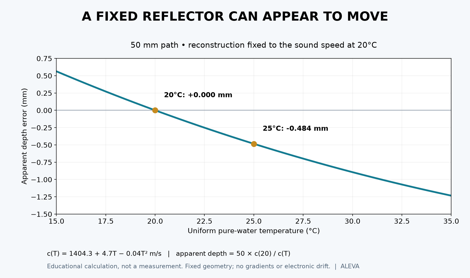
Figure: educational calculation over 15–35°C. The reflector and reference plane are fixed, while reconstruction keeps c(20°C). Real fixtures add effects excluded from this model.
Amplitude has a separate measurement chain
Correcting the water-path timing does not correct hydrophone sensitivity. A peer-reviewed 2025 study by Wilkens, Weber and Twiefel characterized four hydrophones at different water temperatures. Temperature dependence differed by hydrophone type and frequency; even the direction of sensitivity change was not universal [2].
For a hydrophone measurement, record the calibration temperature and the test temperature. Apply a correction only when it is justified for the instrument and frequency range, or include the relevant contribution in the uncertainty budget. Do not transfer a coefficient from one hydrophone to another, or interpret the study as a temperature coefficient for the ultrasound probe.
A practical test separates three questions
Is the propagation path stable? Record water temperature near the acoustic path, reflector position, immersion geometry and the method used to identify echo arrival. A single sensor cannot prove a large bath is spatially uniform. Establish a temperature-stability criterion appropriate to the required timing or distance uncertainty before comparing captures.
Is the acquisition chain stable? Preserve the transmit settings, receiver gain, sampling configuration and raw RF data. Where the hardware permits it, use a separately characterized electrical reference to investigate electronic timing or gain changes. That reference can help isolate electronics; it does not validate the acoustic stack.
Does the probe response change after those contributions are accounted for? Record probe housing temperature and time since power-on separately from bath temperature. Repeat the sequence at defined plateaus, then return to the starting condition. An irreversible change, a reversible temperature dependence and a fixture-position change call for different investigations.
Set acceptance limits before applying corrections
A useful engineering sequence is to define the reference plane and operating configuration, retain uncorrected captures, apply a documented correction, and then evaluate the residual against a predeclared limit. Keep both raw and corrected results. Tuning a correction until one dataset passes conceals whether the model transfers to another temperature, probe or day.
Temperature uncertainty also propagates into distance uncertainty. For this model, dc/dT = 4.7 − 0.08T. Near 20°C, the fixed-reference apparent-distance sensitivity for a 50 mm path is about −0.105 mm/°C. This local derivative helps allocate a temperature contribution; it is not a complete uncertainty budget. Sensor calibration, thermal gradients, reference-plane location and echo-picking repeatability still require separate treatment.
There is a trade-off: tighter bath control can simplify comparison, while a validated correction can accommodate a wider test range. The correction approach creates additional obligations to characterize temperature, document model limits and verify residuals on independent captures. Neither approach supplies a universal warm-up duration or a device thermal-safety limit.
What an OEM should receive
For a custom ultrasound probe development handoff, request a test record that includes the acoustic reference plane, bath and probe temperatures, operating configuration, calibration references, raw captures, correction version and acceptance criteria. A manufacturing comparison becomes more interpretable when the next team can reproduce the measurement boundary.
The decision is whether the probe meets its specification under defined conditions. A corrected trace is useful only when the correction and its uncertainty are as reviewable as the trace itself.
References
Lubbers J, Graaff R. A simple and accurate formula for the sound velocity in water. Ultrasound in Medicine & Biology. 1998;24(7):1065–1068. Peer-reviewed foundational source.
Wilkens V, Weber M, Twiefel J. Temperature dependence of the sensitivity of hydrophones for biomedical ultrasound exposimetry. IEEE Transactions on Ultrasonics, Ferroelectrics, and Frequency Control. 2025;72(3):362–369. doi:10.1109/TUFFC.2025.3527625. Peer reviewed.